

TL;DR Wanted a flicker free photo light. Did not want to spend money. Built one with spare parts. Learned some stuff along the way. Photo samples at the end of the article.
Reason to Build
Wanted a constant flicker free light source that could be used for photos or video to replace the light I was using that controls brightness with Pulse Width Modulation or PWM. Using PWM is great for everyday usage but not the best for photography where it limits the ability to use a high shutter speed to freeze motion. The secondary goal build the light with parts I had on hand. To keep the light from flickering I chose to run them straight from 12 volts. By opting to run them at full brightness I could use toggle switches directly between the power supply and LEDs and keep the parts list simple.
Electronic Components
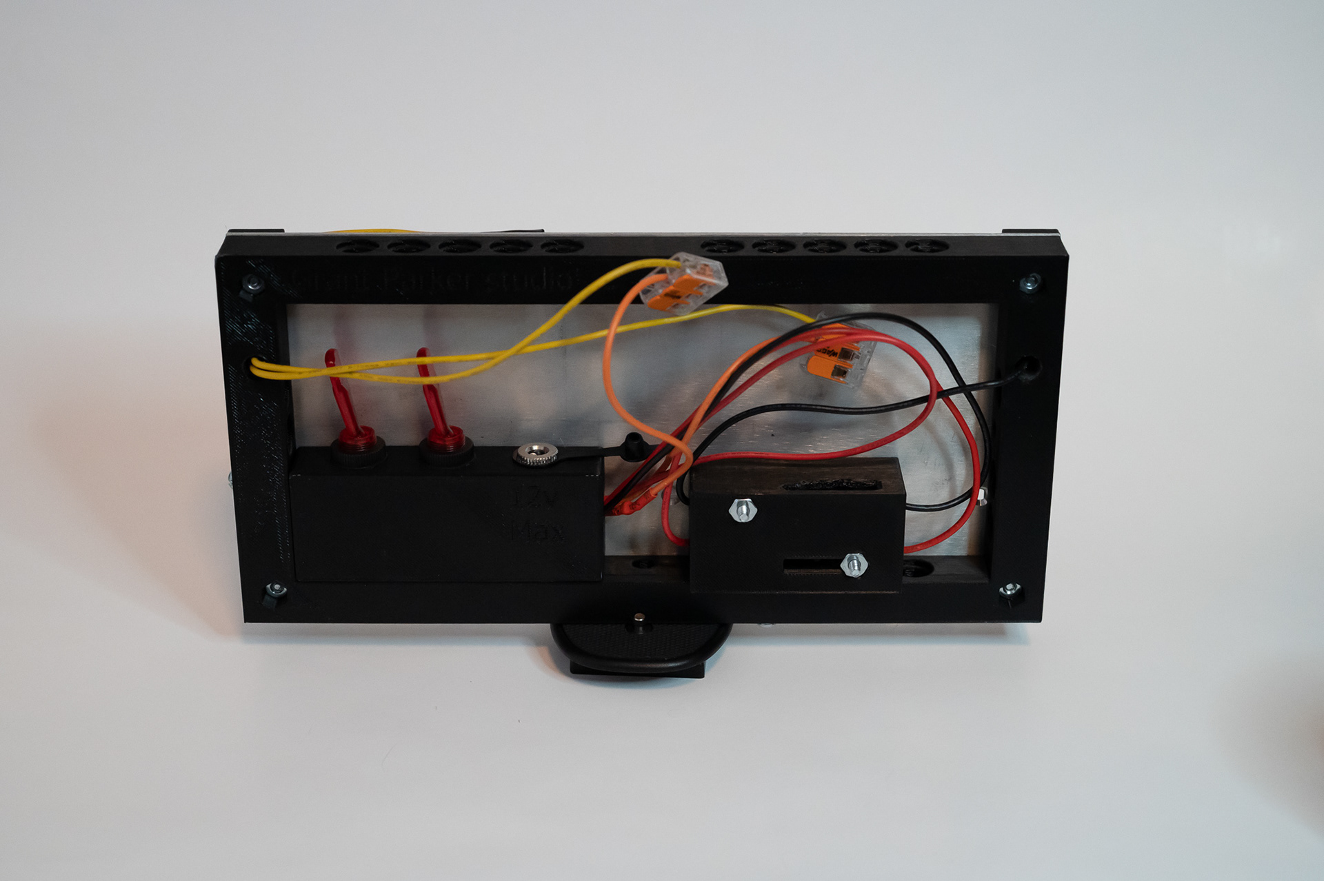
To get started I raided my parts storage for LED strip, toggle switches, wire, power supply, and a power connector. I had some warm and cool white LED strip and opted to use both to balance the color. Thankfully I had two 12 volt compatible switches that I had bought when RadioShack was going out of business so that I would be able to turn on each LED strip individually. All of the wire is 18 awg from an old PC power supply that I had disassembled. Since all the power supples I have use standard barrel jacks I went back to the parts bin and found a female barrel jack to use.
Hardware
I planned to 3D print most of the parts for this project but choose to use a piece of scrap aluminum panel as the main structure of the light. I choose this mainly for structure but also give the heat from the LEDs a better place to go than just a plastic part. To hold it all together I had some 3/4 inch 6-32 screws. I also found some 1/4 inch nuts to be able to use a standard tripod mount for positioning the light. With the electronic components and hardware I could not print planned out, I moved to designing the rest of the light.
Designing the 3D Printed Parts
Main frame - I designed the main frame with a pattern of holes on each side so that I could design the modules for the other components separately and so that they could be changed out if needed. I added in holes for routing the wires to the front, holes and nut retention for the front plates, and slots for 1/4 inch nuts in two of the sides.
Magnetic front plates - To hold the main frame and panel with the LEDs on it together I designed two front plates for the screws to go through. While I was designing these I had the thought to include some holes for adding in magnets. I did this to be able to have a mounting point for adding a diffuser or filter to soften the light in the future.
Switch Box - Made one box to hold the switches and power input. Should have added in slots for the nuts forgot as I was designing it that I would not be able to access the nuts to hold them in place as the aluminum panel would already be in place. Thankfully a small dab of super glue held them without an issue.
Assembly
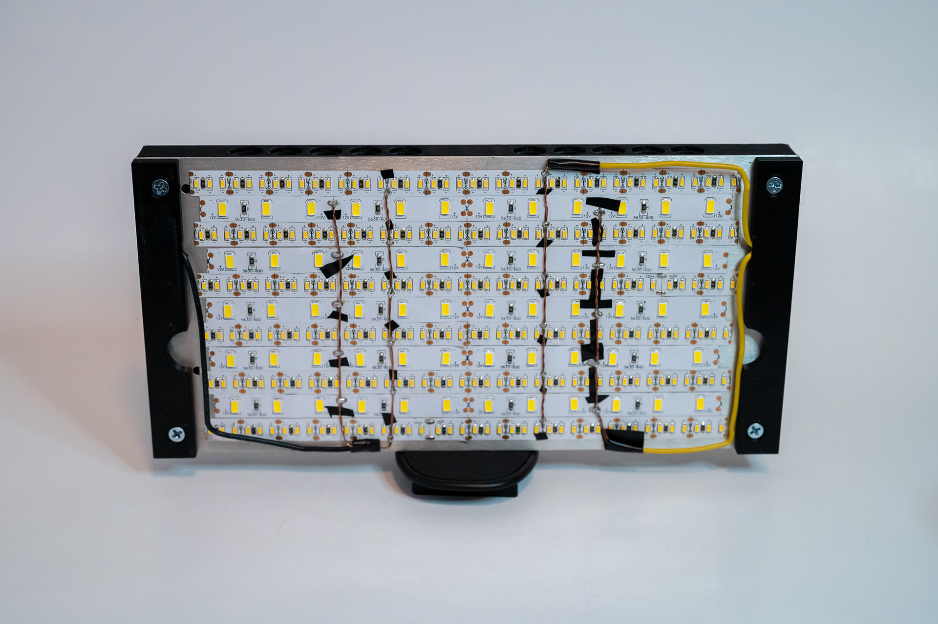
Once I got the main frame and the magnetic front plates printed I began assembling and wiring it all together. The only modification I need to make to the aluminum panel was to drill holes for the wire routing and main screw that hold it all together. To do this I used the main frame to drill the holes in the right places.
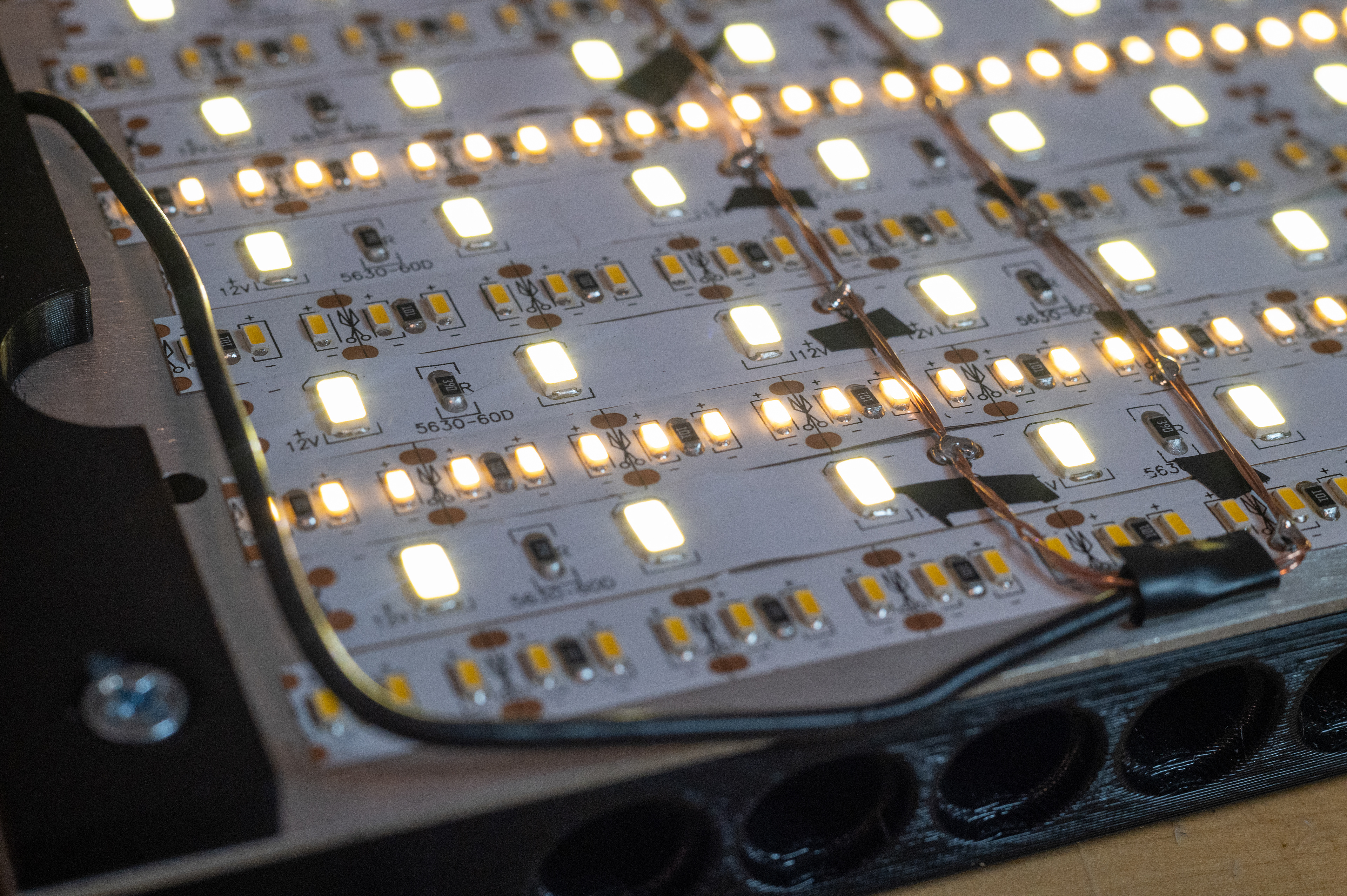
The wiring I would say is less than standard with electrical tape blocking the contacts for the opposite connections. I soldered the Led strips in parallel like this for 2 reasons. The main reason is that it was much simpler than to solder a bunch of small wires to each strip and the second that it more evenly distributes the power and reduces waste resistance over the entire length of the strip. This probably would not have impacted the length used here but I have seen LEDs get dimmer as the length of the strip increases because of the resistance of the strip itself. With the lights soldered I used my bench power supply to power them at 12 volts and learned that the current draw was hitting over 3 amps. This current draw is higher than the wire rating I am using and the LEDs were generating a massive amount of heat. I decreased to 11 volts but the current draw was still higher than I wanted. I made the decision to just cut 3 of 6 the warm white strips so that they were unpowered since everything was soldered already. This got the current draw under 2 amps with a light level close to what I wanted.
Learning - Measure the current of the length of LED strip BEFORE cutting them for assembly.
Unfortunately, this is where I hit a wall with the components I had on hand and had to order a voltage buck that could handle more than 2 amps in order to reduce the voltage. After getting the voltage buck in the mail I modeled and printed an enclosure (with slots to hold the 6-32 nuts this time) to mount it into the main frame. With that last part printed I was able to get all the components soldered up and the light put together.
Below is the finished product and some test shots using the light.
Assembled Front
Back
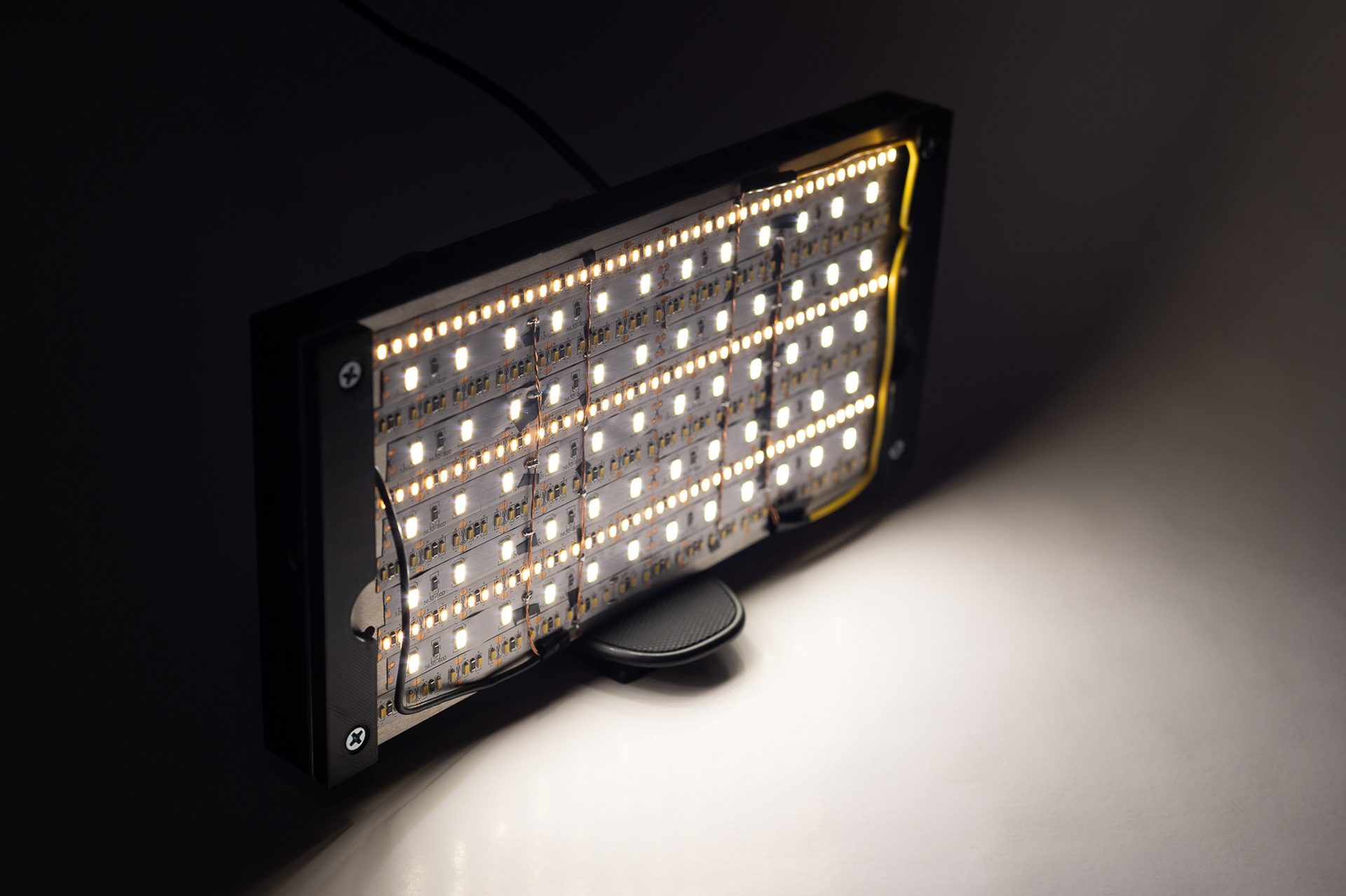
Powered on
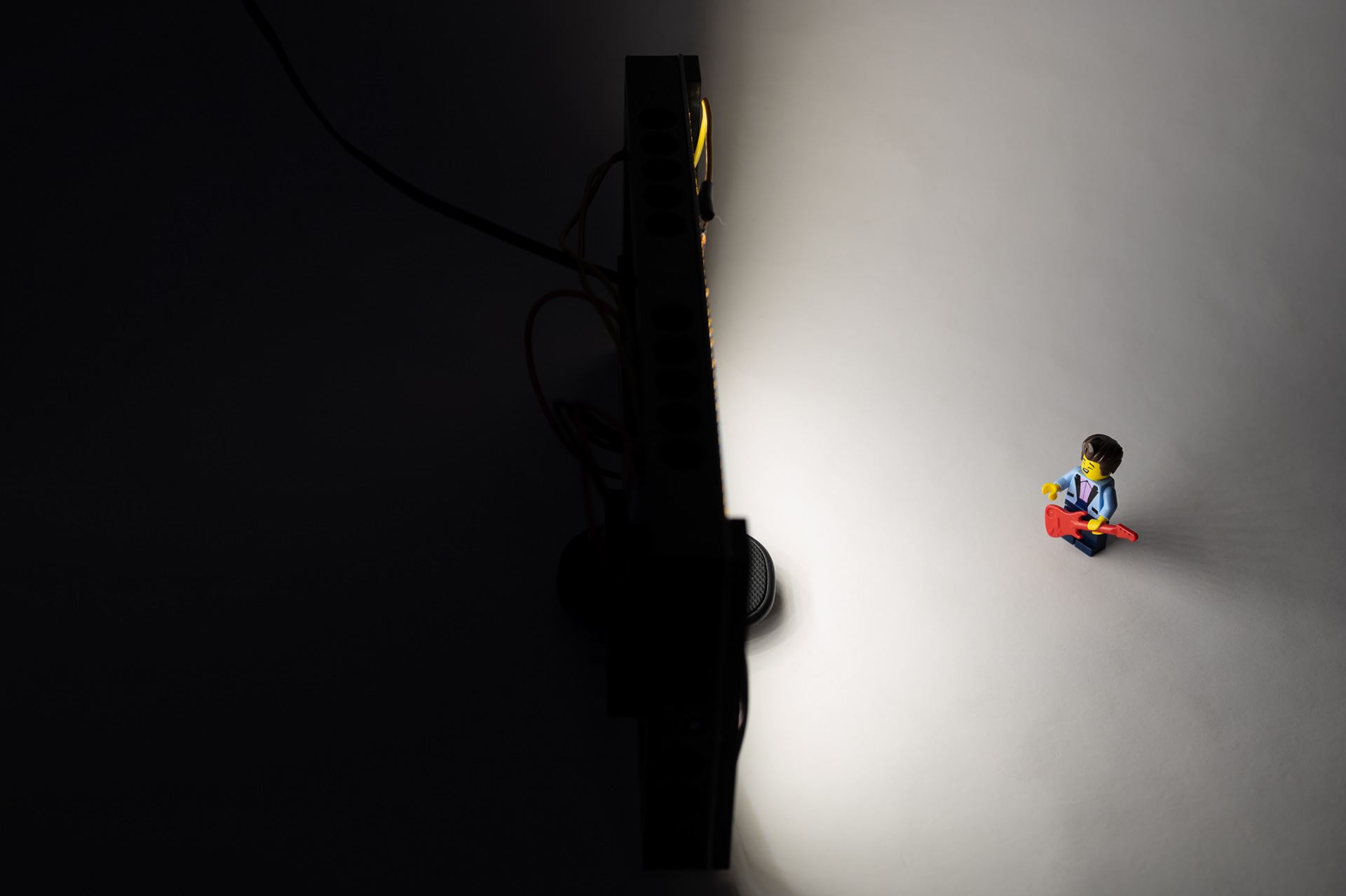
Illuminating a subject - Not sure if he is squinting from singing or the bright light.

Iron Man in midair
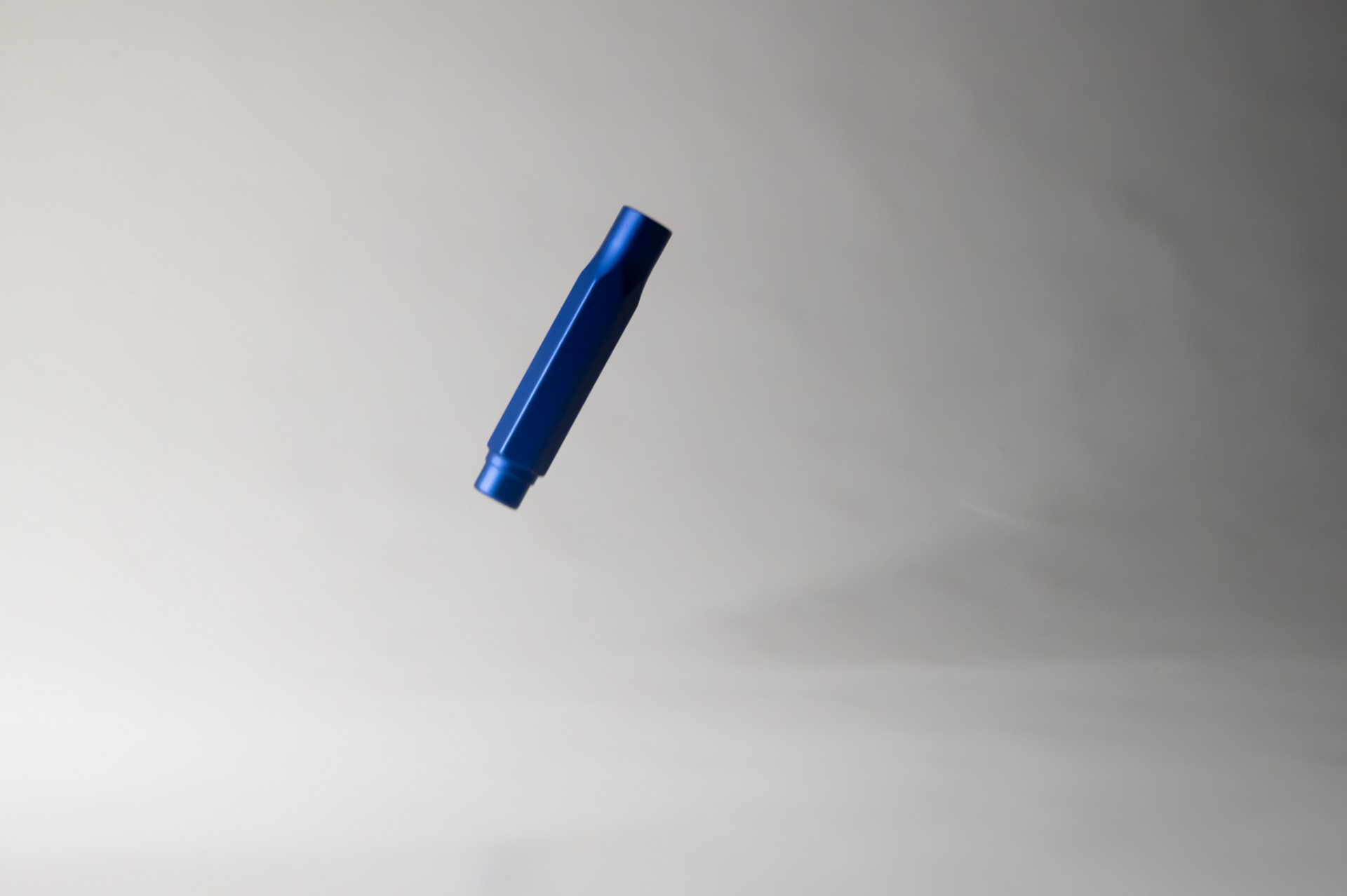
Blackwing pencil cap in midair

Light panel as the only light source
I set out to build a flicker free photo light and feel like this was a great first try at that. I missed my secondary goal as I did have to buy a part but am still happy it was just one purchase. I have enough components to build a second one so another version might be in the future but first I plan to design a diffuser that will attach magnetically to the front.
Thanks for reading to the end and I hope some of my learnings can help you in what you make.